1.Project Overview
In this project we had to make a counter that would count from 0 to 80 and then suspend itself before being reset to 0 with a reset switch. The circuit had to use SSI integration for the tens digit and MSI for the ones digit.
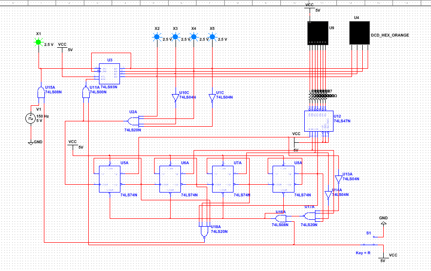
2. MultiSim Circuit
3. PLD Circuit
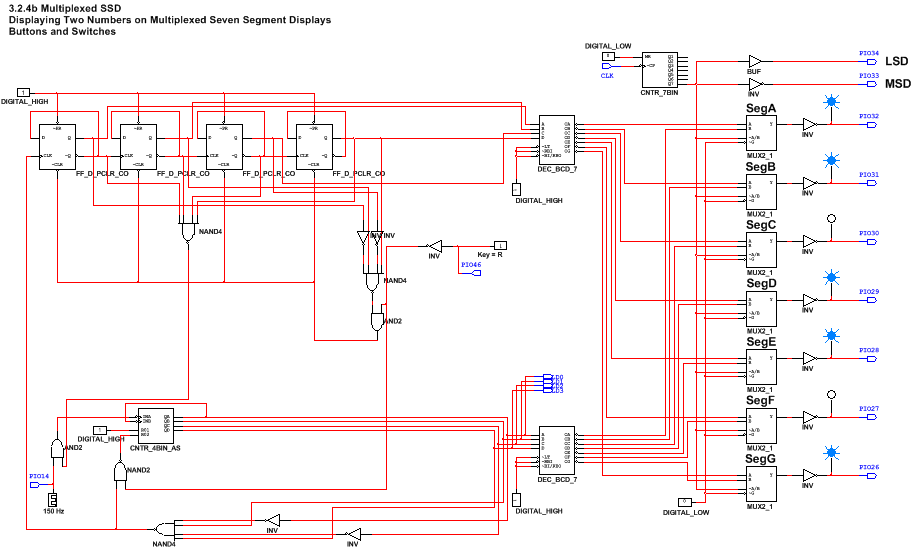
PLD is different from the regular design mode on MultiSim because the designs produced in PLD mode can be transferred onto a programmable breadboard. Pins need to be assigned to all inputs and outputs so that power can be placed to the correct place on the breadboard. An Input connector is attached to a piece that inputs a signal, an output connector is a piece that puts out a signal and does something.
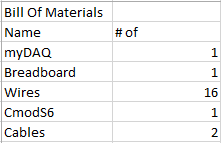
4. Bill of Materials
5. Conclusion
SSI is a type of circuit where each of the individual logic gates are expressed with an IC. MSI circuits do the the same thing as SSI circuits except the circuit is expressed using a gate that performs the same function of all the individual logic gates used in SSI.
The limitations of an Asynchronous MSI counter is that it can only count up and it has to start at 0.
The bread board is transferred power from the wires connected to the 5V and GND pins, the supplies the positive and negative rails with ground and power. The wires at pins 24 and 25 provide the CMOD chip with power. The wire from pin 14 to DIO3 plays as the initial clock and supply's the clock voltage to all the flip flops in the program. The wire connected to pin 47 allows the button to be pressed in order to reset the counter. the wires connected to A-G provides the power to the display to light up the right segments to display the count. DIG1 and DIG0 allows a signal to be put on the seven segment display.
Some people didn't put an inverter after the button input so theirs only counts up when the button is held. I put an inverter after the button input on mine because it counts up when the button is pressed just once instead of having to hold it.
